We pressed pause on the construction of the Outpost project in early 2021 and onboarded a new contractor to see us through completion. Although this isn’t the first time I’ve encountered this situation in my twenty five years practicing architecture, there are always new lessons to learn in these transitions.
Read MoreFresh Inspiration from My Library
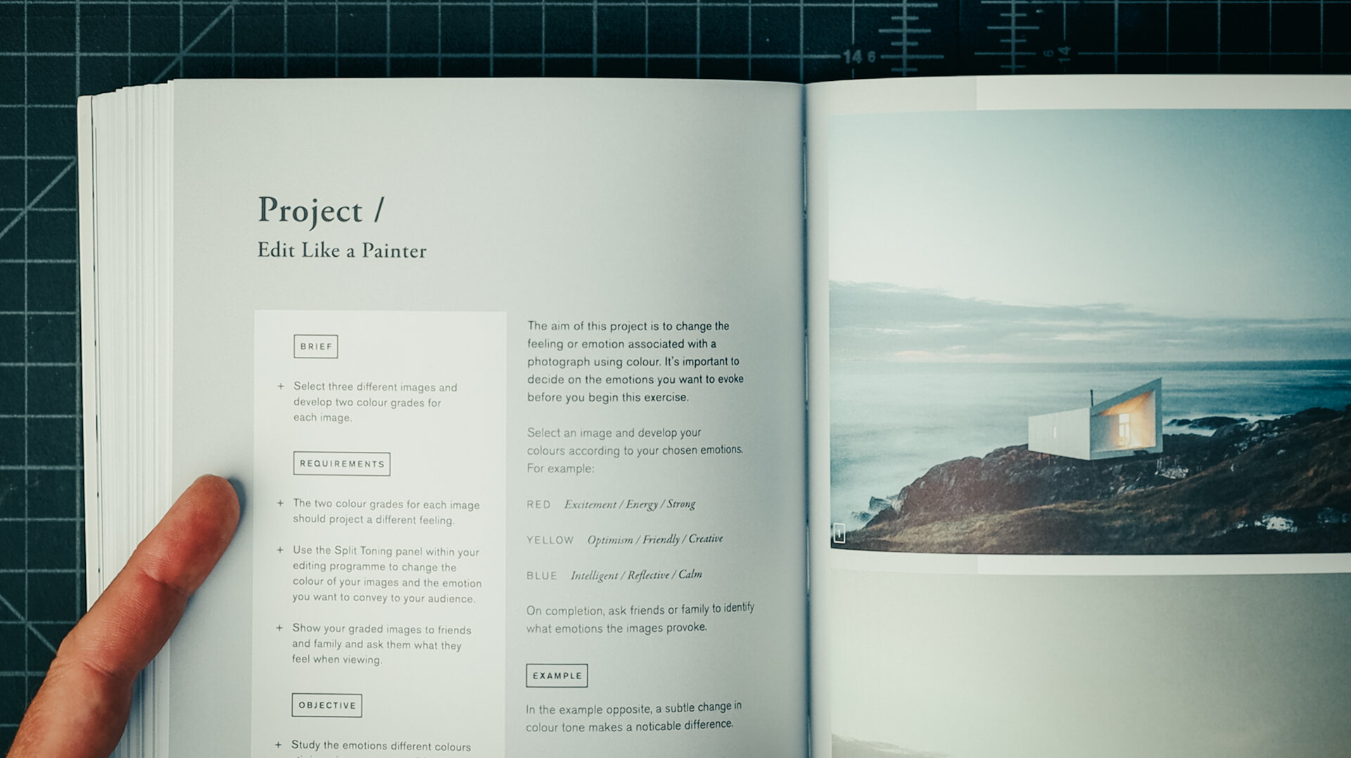
Books have always played a role in my design process. I recall many hours spent in the architecture library at university mining the shelves for new ideas. In daily practice one has to actively make space for seeking out fresh ideas and inspiration. I’ve found that some of the most inspirational books have nothing to do with architecture, they're in adjacent or completely unrelated disciplines. By consuming a variety of source material I find it easier to make connections and surface new ideas overlaying the work of others with problems I’m actively trying to solve in my architectural work. This is called bisociation, defined as : the simultaneous mental association of an idea or object with two fields ordinarily not regarded as related. A pun might be the simplest form of bisociation.
Here’s a list of the books highlighted in the video, in order:
THE PHOTOGRAPHY STORYTELLING WORKSHOP - Finn Beales
MECHANICS VEST POCKET REFERENCE BOOK - John Wolfe & Everett Phelps
PRETTY MUCH EVERYTHING - Aaron James Draplin
HABITAT - Tom Hegen
A TALE OF LIFE + CRAFT - Garde Hvalsøe ( 2020 ebook version slightly different, but free to view )
HOUSES - Sean Godsell
HELL YEAH OR NO - Derek Sivers


Because my inspirations and collecting tastes are always evolving, I keep a record of what's inspiring me "NOW" on a dedicated page here on my site. When it's time to update it, I simply copy it so I don't lose record of it and can keep it as a running archive of how things have changed over time.

Revising + Updating the Drawing Set
A recent site visit + client request sets in motion a process every architect is familiar with: redesign + revisions. This is my process for solving real-world architectural problems, from sketching to updating the drawings and documents.
Revisions begin by clearly defining the problem and constraints governing the redesign. All design benefits from constraints, without them the possibilities are limitless. As we’re in construction the restrictions are numerous: there are budgetary, esthetic, physical, legal, and functional considerations. And, of course client preference is chief among them. I’ll often work through solutions that are less than optimal to illustrate shortcomings and to help move the design process forward. Below are a few examples of the initial solutions I developed.
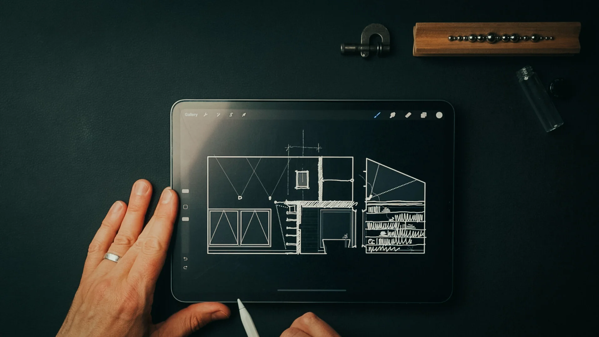
Sketching Solutions

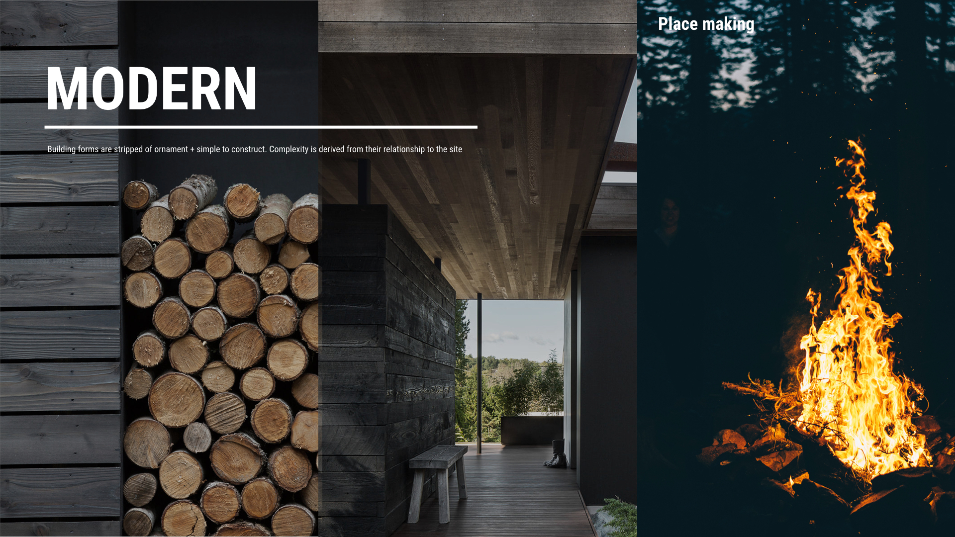
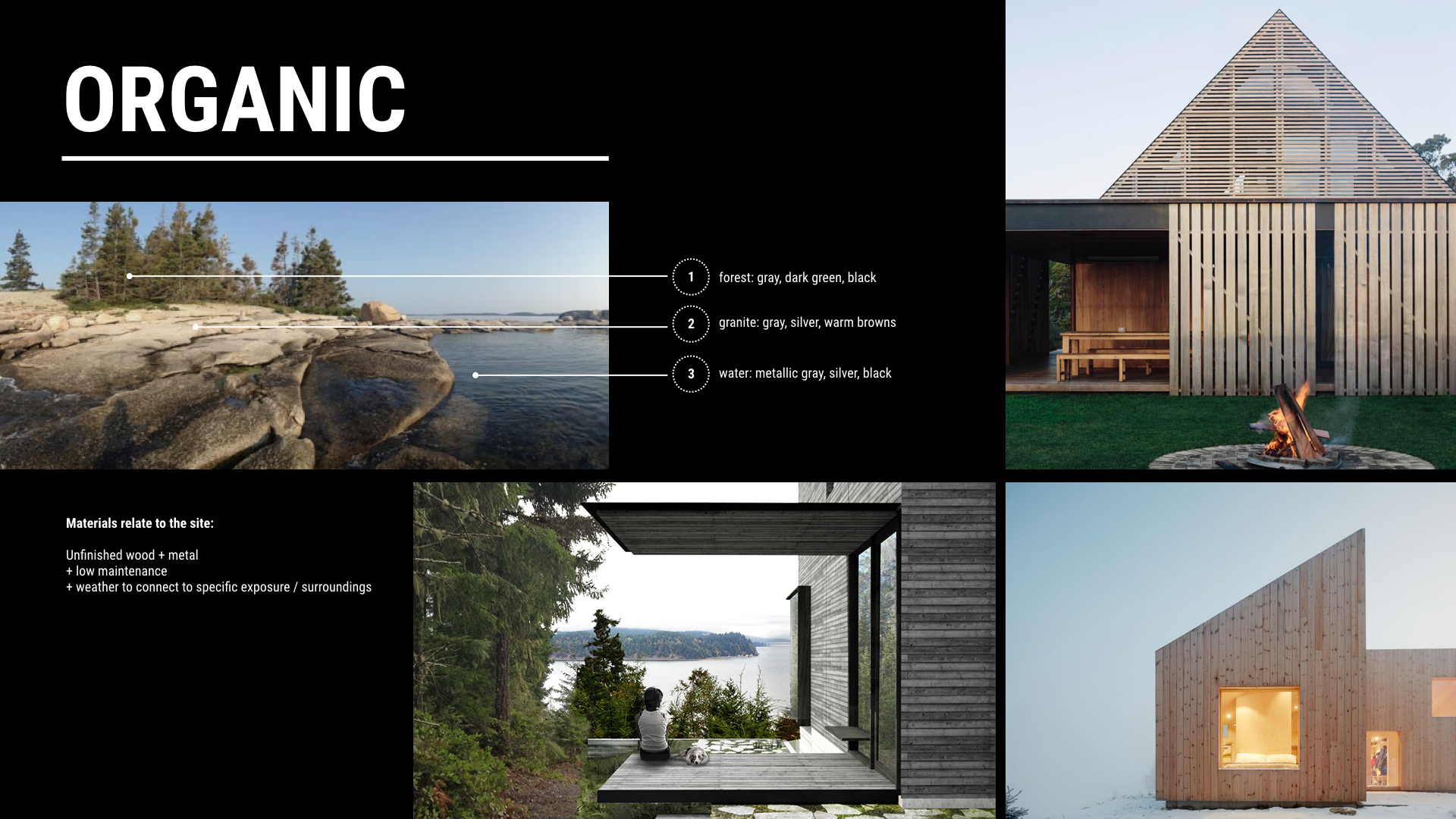
Material Palette for inspiration
A ladder clearly takes up the least space in the room, but it’s also the most difficult means of accessing the loft space. As my clients imagined cleaning it and bringing books to and from it, the use cases narrowed. Even though it may be possible to recapture extra space in a home, if it’s not useful or easily accessible, the cost-benefit is questionable.
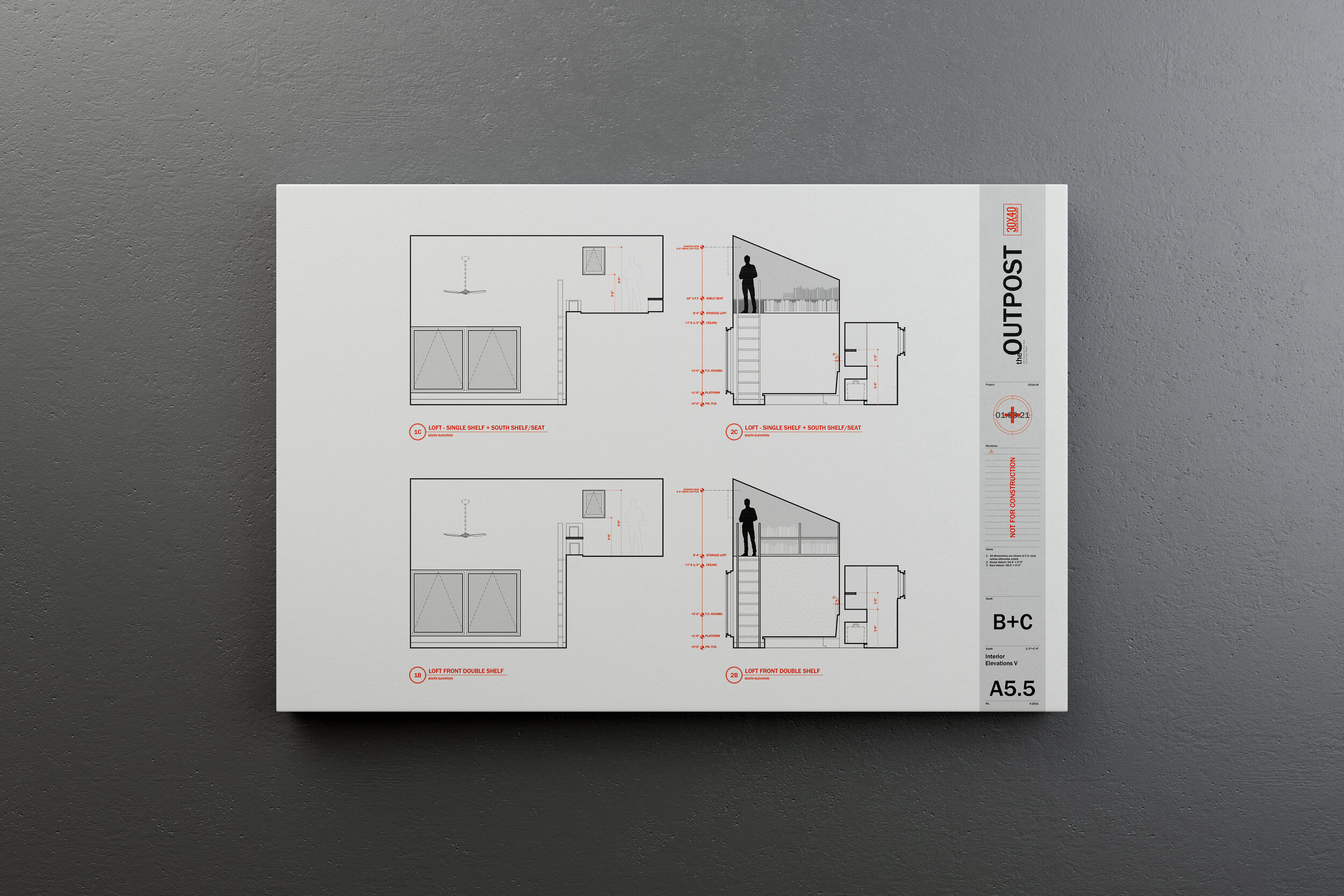
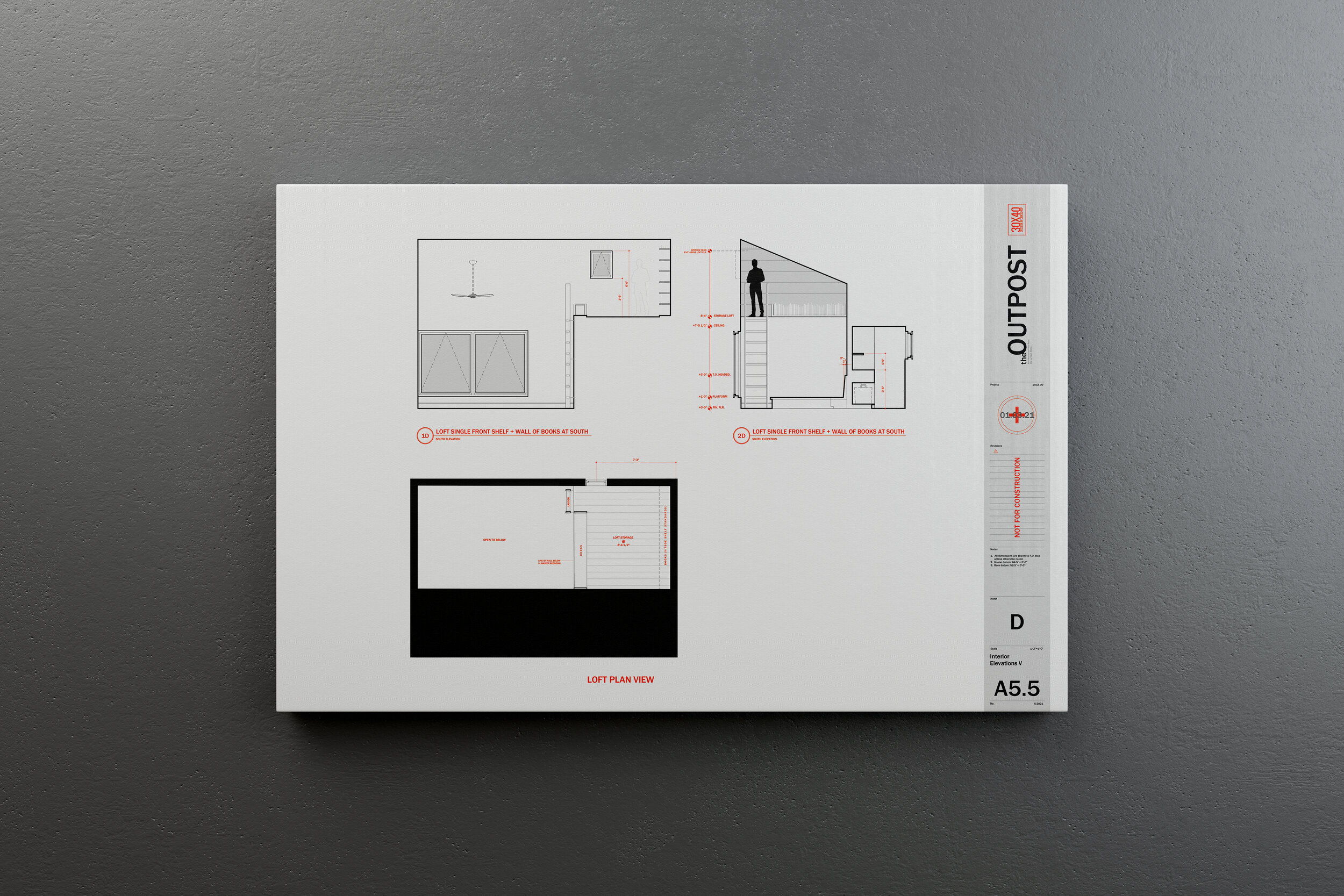
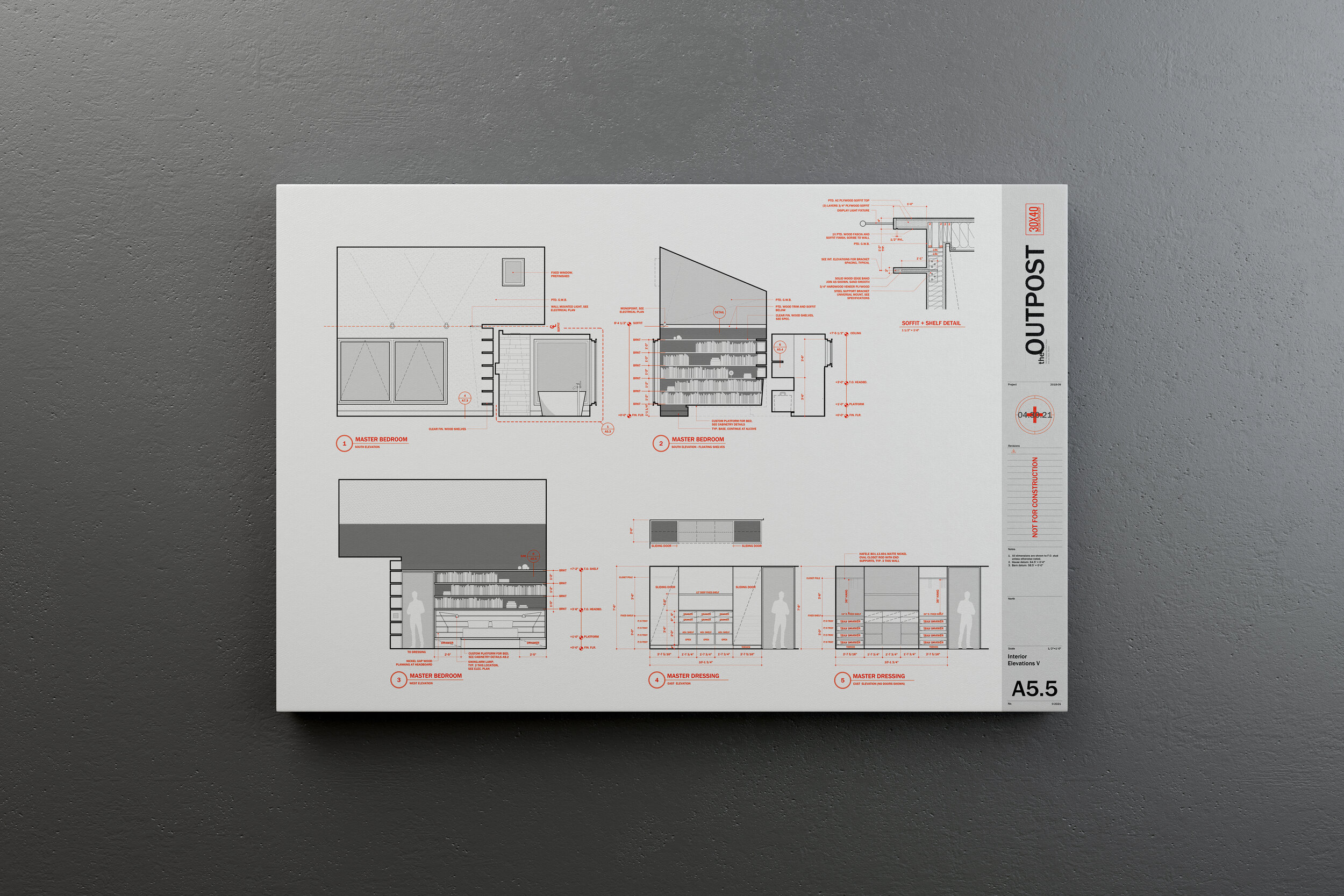
As we worked through the options, this need for book storage suggested a new opportunity. By shifting the pocket door entry to the north and creating an alcove for the books on the main level we solved a few problems at once. The books found a natural home within arms’ reach and this singular, sweeping gesture on the south wall of the room also created a soffit above for display, increasing the perceived volume of the room and it allowed us to add a small eyebrow window to let light in from above. The soffit and shelf repeated a motif we had used elsewhere on the interiors whereby we nest smaller volumes within larger volumes of space.
Idea becomes sketch. Sketch becomes presentation drawing. Presentation drawing becomes construction drawing. And now, we build!
Outpost Updates - July 2023
To see all the latest progress + the current interior design iteration check out the links below:
Latest Blog Post: Interior Design with an Architect’s Eye
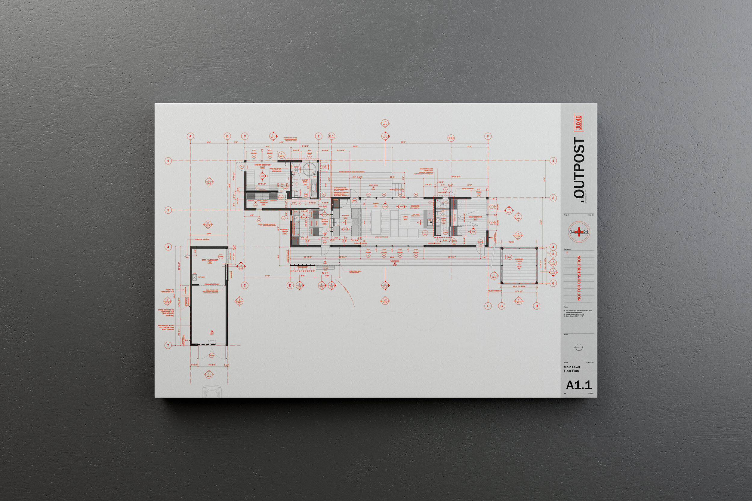
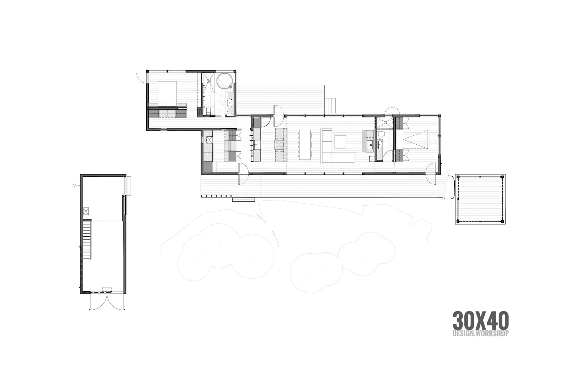
Download the floor plan: Architectural Floor Plan Working Drawing

Door Jamb Head Reveal Detail

Door Jamb + Base Reveal Detail
Field Report: Framing the Island Outpost
The Outpost project has entered the rough framing phase. This is the point where that initial sketch of an idea is rendered in physical form. For an architect, it's probably the most exciting part of construction and it's taken us many months to get here. Site and foundation work are time consuming and embody a lot of effort, but progress is often slow and much of the work remains hidden in the finished home. By contrast, framing moves quickly and there's much to coordinate between the trades: plumbers, electricians and mechanical subs.

The culture of HGTV has tricked us all into believing that construction happens in the space of a 30-minute show segment. But custom design + construction takes time to complete. And, custom construction on an island takes much longer (I'm learning). That's because building on an island is subject to an entirely different set of rules.
All things being equal, given the choice between plentiful, profitable work on the mainland and work on an island, most contractors have been choosing the work that's easier to access and execute. That's not something I had fully anticipated at the outset of construction and it's proving a difficult problem to solve. The building boom here in Maine has caused a significant labor shortage and that's hindered our ability to secure subcontractors willing to make the journey out to our remote site.
There are no hardware stores, or places to run to if you need an extra bag of concrete. Everything we build with comes from off-island and thus, bringing the necessary materials to the island requires a special weather window and, if it's a load delivered by barge, the right set of tides to land and leave the beach. Winter wind and heavy seas have conspired against us more than a few times too.
The work continues though and I'm thankful for the dedicated crew acting as my hands in the field to realize these ideas in spite of the wind and weather. So too, for generous, supportive clients - dear friends by now - who patiently watch as their home takes shape. To navigate these opposing forces and turn them to your advantage takes skill, hard work and the work of many. And, perhaps that's the reason the creative satisfaction in the end is so great.
My sincere thanks for watching and following along. It really is as much fun as it looks!
South end, guest bedroom looking north
Drive approach looking southeast - Feb. ‘21
North end, entry looking south
Western approach, looking northeast
Southwest end, looking northeast
Drive approach - March ‘21
Master suite looking northeast
View from entry looking east
Living space, looking north toward (future) kitchen
Lighting Design + Drawing Tutorial - My Process
We can build a home from a set of five drawings or a set of fifty, one provides a lot more control over the finished product. Whether your plan set is five or fifty, one of the must-have drawings is an electrical plan. Follow along in this video as I design + draw the architectural lighting plan for the Outpost project. An electrical plan is an essential drawing in every architect’s toolbox, it shows the fixture types, switching, receptacle locations, all the necessary electrical devices + equipment we need to plan for in our architecture. Designing it in coordination with the other essential building systems: architectural, structural, mechanical and plumbing affords us optimal control over the design.

Hidden elements in a project - beams, ductwork, vent stacks - can adversely impact the placement of the visible elements - light fixtures, for example - which is why we plan for them early in the design process. Drawing and overlaying each helps us to identify conflicts in the studio and on paper where it's much more efficient and cost-effective to make changes. See how the abstract concepts of ambient, task + accent lighting are accounted for and applied in the design of the Outpost, a remote, off-the-grid residential project here in Maine.
Resources:
How I Work Remotely with Clients
Sharing my process for how I work remotely with clients. Because social distancing protocols have forced us all into new working environments, I thought now would be the perfect time to share how I make, present and catalog all the revisions every design project requires from a distance. Using the Outpost project as a guide and a recent request for a few design modifications, you’ll see the process unfold from idea to presentation to documentation.
Stay safe out there and, don’t miss 15:28, it’s my favorite sequence…!


If you’re hunkered down and looking for reading material, here’s everything in the stack of books at the end (top to bottom):
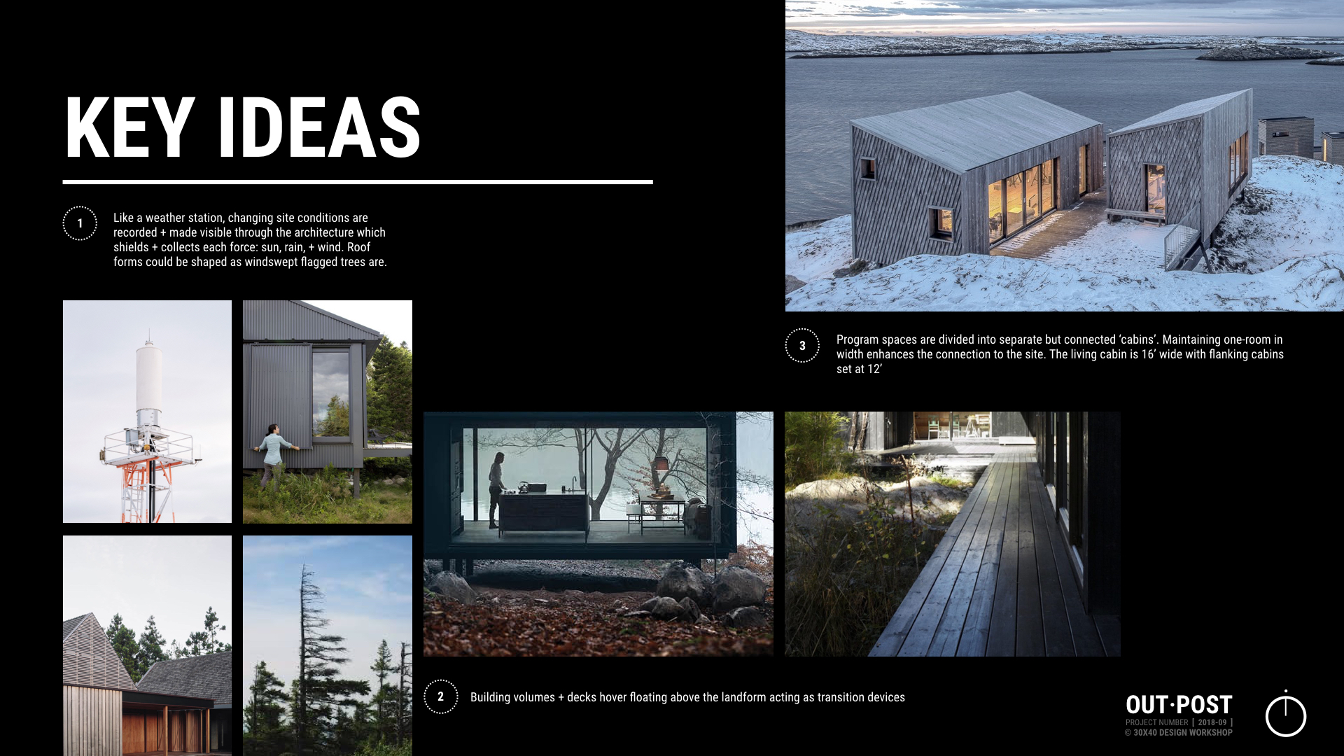
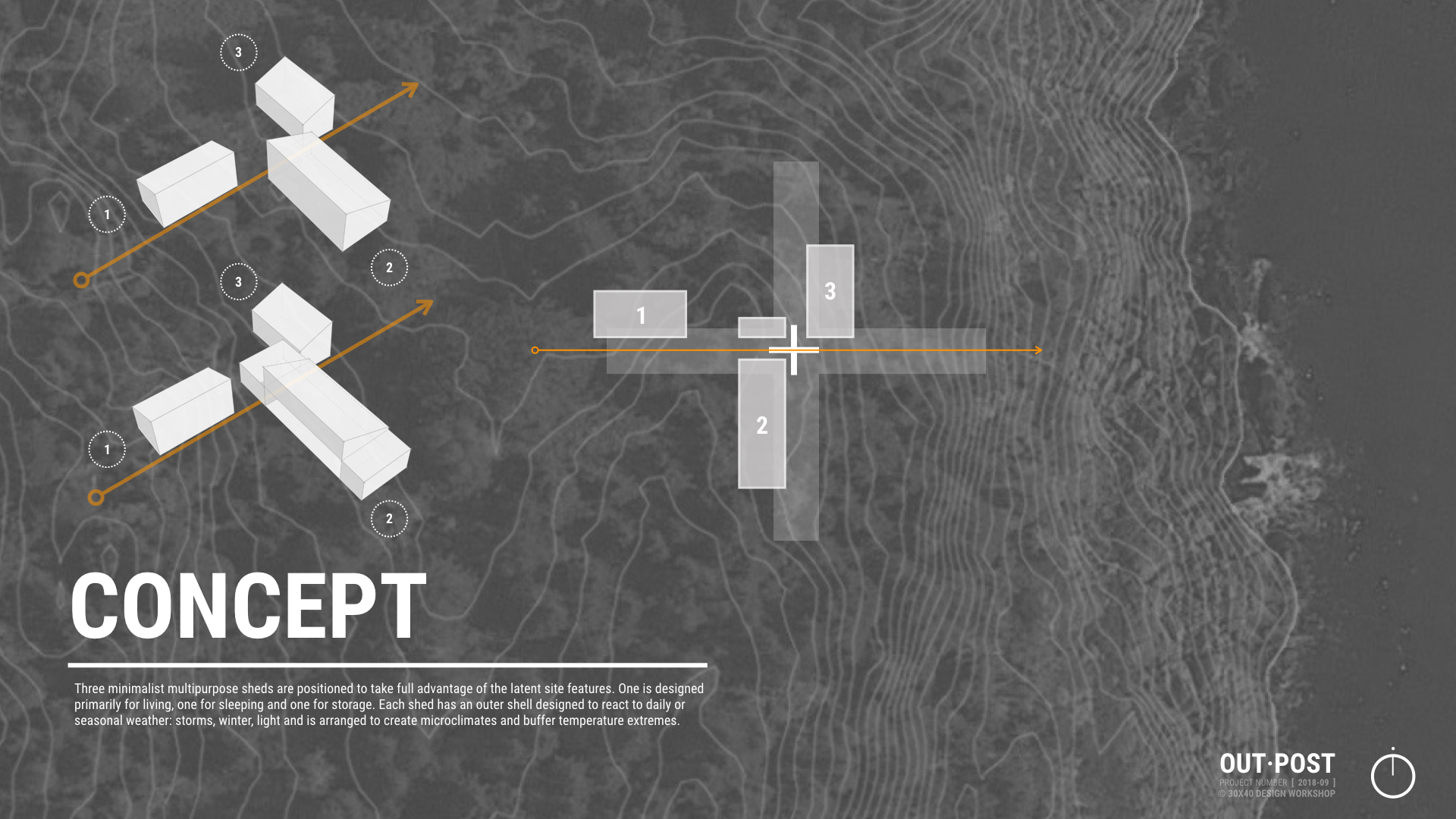
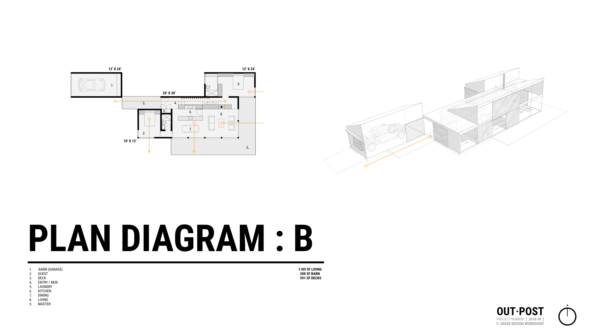
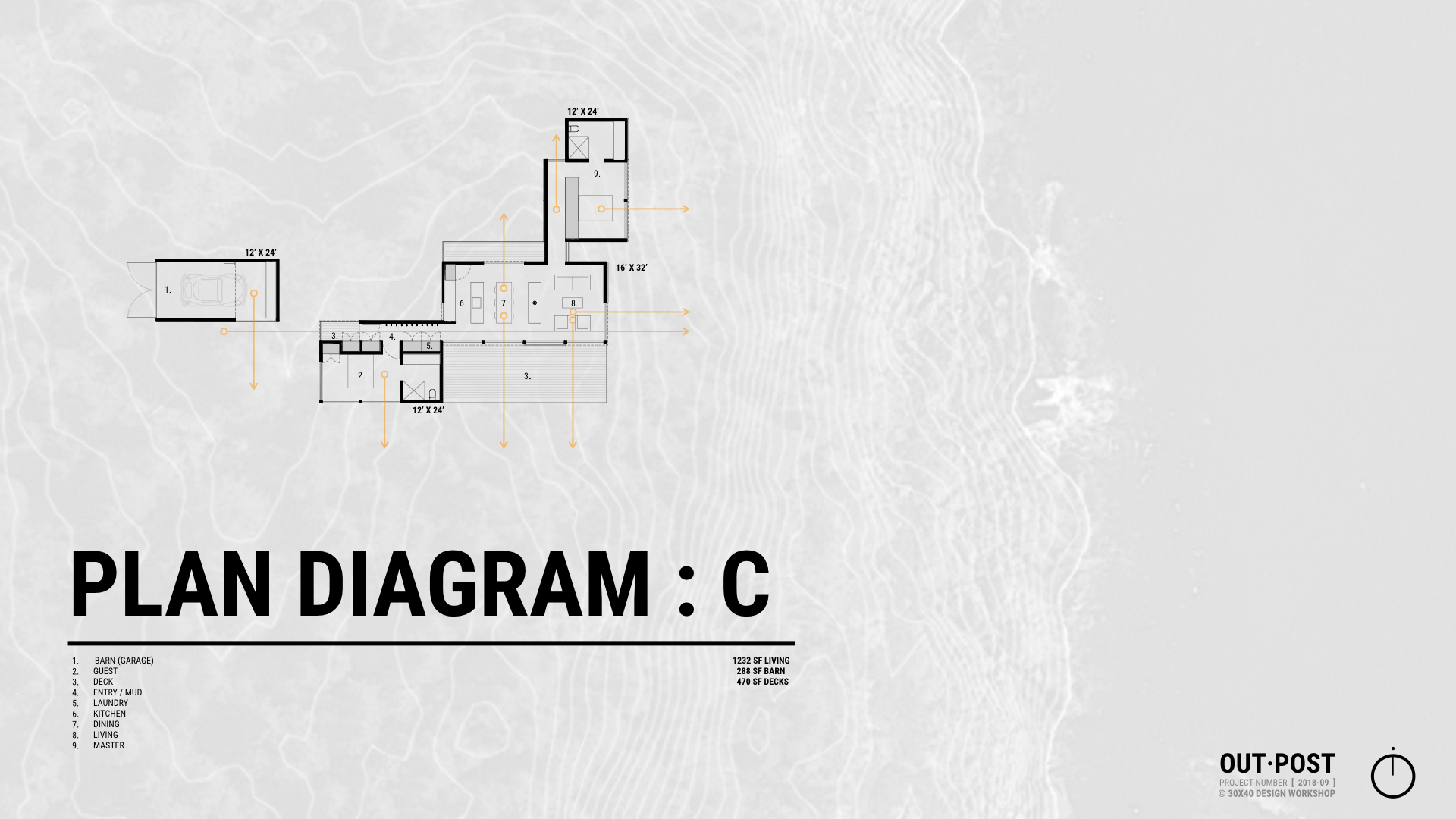
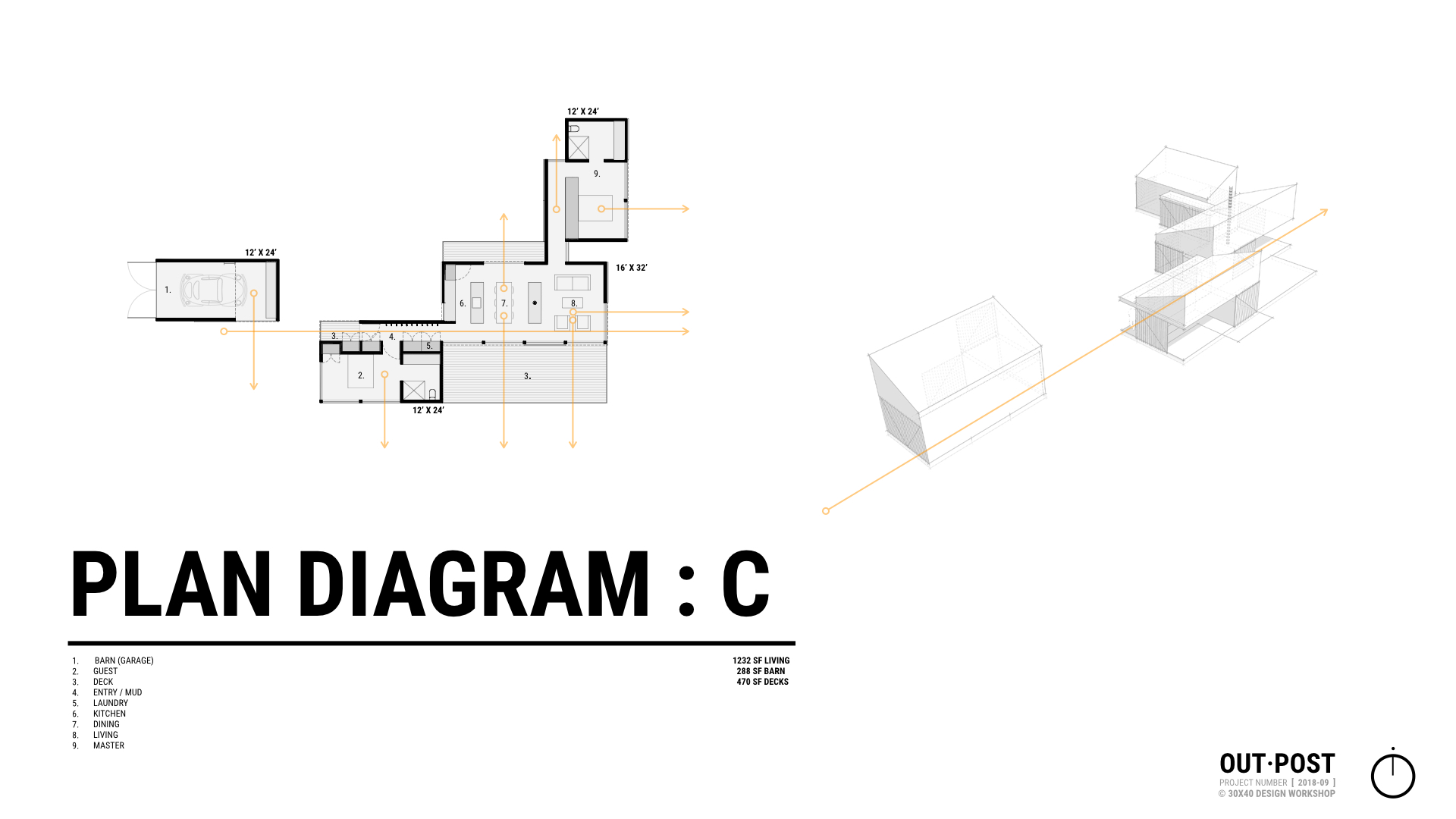
Schematic Design Presentation - The Outpost
Below are the slides from our meeting which was held on-site on July 3, 2019. The presentation was built in Keynote and presented on my MacBook Air (a larger screen would’ve been a better choice, alas, my MacBook Pro had a battery issue!)
Additional details:
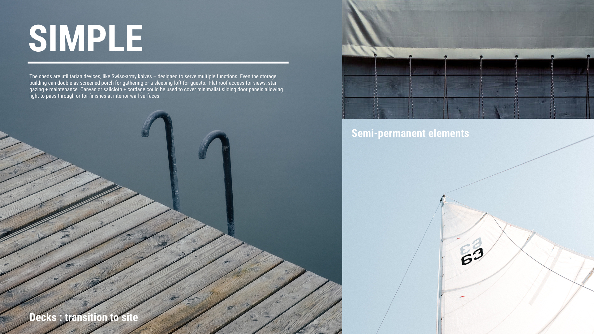
Slide images: combination of visuals pulled from the project’s Pinterest board + unsplash.com
3D model: SketchUp Pro 2018
Diagrams: Keynote
Plans: AutoCAD LT

Site Visit Kit

MacBook Air (MacBook Pro with larger screen would be ideal)
Muji Pencil Case + Sign-pen + Kuru Toga pencil
Surveyor’s Flagging (to lay out building corners)
Small scale

DJI Mavic Pro ( Fly More Combo )
If you enjoy these videos, you can support 30X40’s work on YouTube by investing in a course, a toolkit or a digital tool. Many thanks!
One Book Every Designer Should Own
A review of one of my all-time favorite books; one I think every designer should own. Part review and part personal reflection, it's a continuation of my previous video on goal setting. As I struggled with my traditional goal setting exercise this year, I stumbled on a new methodology and consulted a formative book in my library for guidance. In this video I share how that book has shaped my architecture practice and my approach to life.
I view books as the raw materials of creativity. Looking at and learning from the work of others is crucial to the development of your personal style and sampling from every possible source you can: graphic designers, authors, engineers, sculptors, every field is essential. The deeper your understanding of what’s out there the more source material you have to draw upon and the more things you can smash together to craft your own style. Study those you admire, not to replicate their style (you don’t want to look like them) but to see like them.
A special thanks to my grandfather, whose counsel I miss each day, but who will always live on in my studio and work.
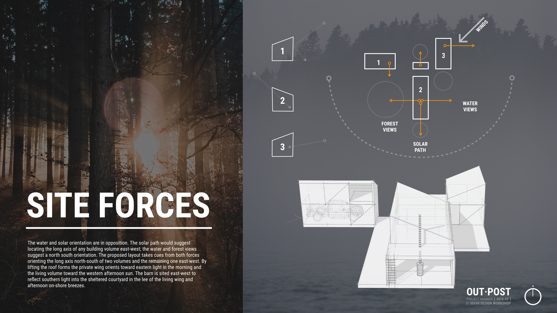
Architectural Design Process : Form, Orientation and Sunlight
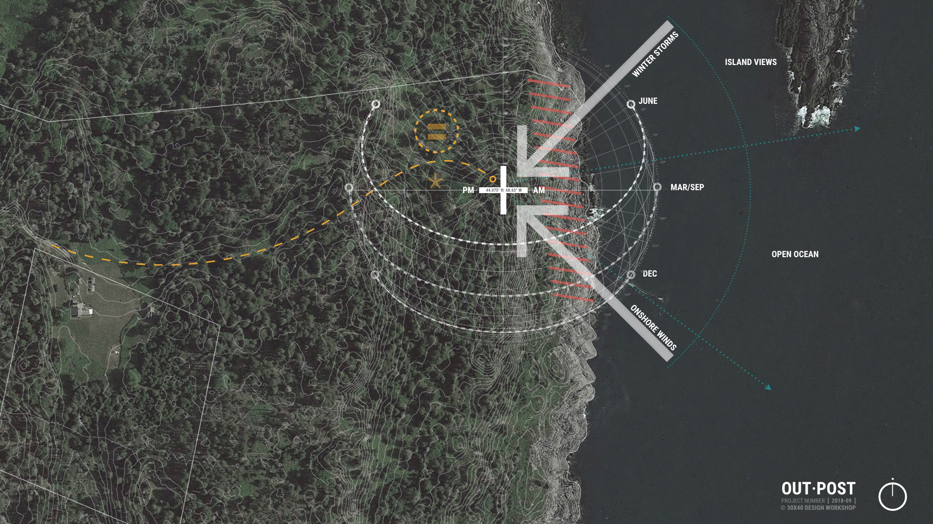
Learn how you can use the Sun to locate, orient, shape, and inspire the details for your architectural design. In this video, I walk you through the design process for a project whose form, orientation, and details were all developed by carefully analyzing the solar path on the building site.
Resources mentioned:
**White pen I'm using (+ loving)
**Get it Right with Amelia Lee - The Undercover Architect (podcast)
**Sunseeker app
Architectural Plans Tutorial - How I Draw Floor Plans
Want to see all of my tools + gear?
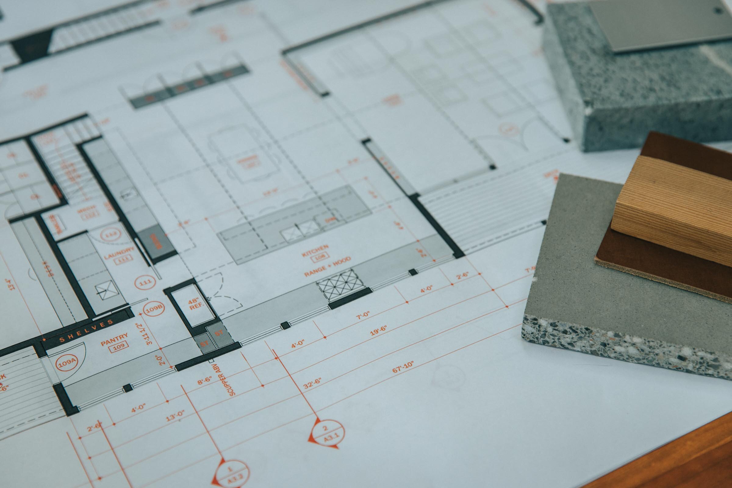
In this architectural plan drawing tutorial I'll walk you through the exact settings, line weights, pen styles and layers I use to develop digital architectural drawings for my residential architecture practice. We’ll focus on how to recreate the floor plan you see in the thumbnail image below. You'll also learn how architects choose what to draw, how we approach our drawings conceptually, and how we organize information.
I use AutoCAD for all my drawing work right now, but you can do this with any tool you have on hand: pen, pencil, Revit, another BIM software, whatever you choose. Tools don’t make the drawing, you do. I use probably the most primitive form of CAD there is, Autocad LT; so that’s proof in itself that you don’t need multiple thousand dollar BIM software to make nice drawings. Use whatever tools you have available.
An architect’s job is to order things and this certainly extends to our drawings too. There’s the organization of the linework on the page - the layout of the sheet - and there’s also the order of information that you’re depicting - the overall drawing hierarchy. Each requires that you know exactly what you’re trying to communicate. Now, I want to keep this simple for this tutorial so I’ll really just be going over how I draw floor plans but the principles apply to all the different types of drawings. The goal of a floor plan is to show the relationship of the spaces to one another, all the physical features of the interior and exterior spaces and to precisely describe the real dimensions of those relationships. It also serves as a sort of overall map to show the team of tradespeople – the ones you’re relying on to construct your architecture - where to look for supplemental information. So it’s naturally a diagram; we can’t show everything, we have to decide just what’s important and leave out the rest.
A floor plan is an overhead view of a horizontal cut through the building usually taken at 4’ above the floor level and of course, it’s drawn to scale. And so, the first ordering principle is that the things you’re cutting through – primarily the walls – should always be the heaviest lines on the page. So key concept number one has to do with lineweight, and if that’s a confusing term check the video in the cards for another tutorial where I describe exactly what that is and its importance.
These drawings look this way because there’s a strong contrast between lineweight the very thin lines and the very thick ones. In CAD when we’re drawing we draw on different layers. Each layer is transparent and they stack together to form the drawing. You can control what you see and what you don’t by turning layers on and off. Separating things into layers allows us to modify our lineweights – among other things – to quickly change what’s being depicted as heavy and what’s not. The process of design involves many changes, so keeping things organized on separate layers will allow you to change things efficiently. Now, I like to keep things ultra-simple and for this exercise especially: I set up my layer groups by lineweight, that’s all. Some architects and consultants use hundreds of layers and I suppose in some cases it makes sense assuming you need that level of control, but I recommend starting with just a few. Mine are in a template file that I use to start new drawings and they’re described very simply: from heavy all the way to superfine. I also have a few additional layers which are helpful: one is for annotations – things like text, dimensions and detail bubbles, one for hidden lines – to show something above or below and then one for hatch patterns. I can turn off any of the layers I don’t need, so I can work more quickly or in a less-cluttered environment. So, you may need more or less depending on the type of work you do, but this is a nice simple place to start. Any heavy lines you want to draw, you’ll put on the heavy layer, very thin ones on the superfine and so forth. In this way, it’s a bulletproof system for forcing you to pay attention to lineweight, which is – I think - the most important thing in making your drawings graphically convincing.
My CAD program is setup to print these lines according to their color and color is assigned by layer. So if I’m drawing on the heavy layer, the line is always white and white always corresponds with a certain line thickness. Make sense? White is always associated with a certain thickness which is set in - what Autocad calls - the color table. But all of that is not really important, because whether or not you’re not using Autocad you can simply change the thickness of the line. In Autocad I use polylines to change thickness but there are other ways even in autocad and your software might call it something altogether different. By changing thickness, this adds even more control over how much punch your drawing has and what’s nice is that it’s clearly visible on the screen as having a heavier lineweight. Now, if you start making really thick lines everywhere just appreciate the fact that when you change the scale you’re printing your drawing at, the lines will look thicker or thinner so just be aware of that. For the quarter inch scale residential floor plans I’m drawing here, I like to draw the outer edges of the exterior walls on the heavy layer and add a little extra punch by using a 1” thick polyline. If you make a template drawing with a variety of thicknesses in it, you can adjust to whatever scale you’re printing or working at. If you’re drawing by hand, lay your walls out first, then come back later and add a heavier outline with a softer lead or darker pen.
To get into the nitty gritty, on the floor plan drawing, exterior walls are assigned to the heavy layer and I show them as a 1” thick polyline as I said. The medium layer is very close to the heavy one in weight and so I use it for accenting things like the top risers of stairs, or site retaining walls, or site boulder groupings. I use the ‘light’ layer for floor edges, door slabs, window frames, counters, cabinetry, and plumbing fixtures, while door swings and window sills I put on the superfine layer. Also on the ‘superfine’ layer I put all the wall sub-assemblies, things like stud framing lines or substrates like plywood sheathing or tile backer. But, more on this shortly. Furniture is drawn on the extra-fine layer, floor hatches on the hatch layer, cabinets and counters are hatched differently depending on how tall they are too. Overhead lines are on the ‘hidden’ layer and text and annotations are on the ‘text’ layer, again more on this in a minute.

The next key concept is to use screening. Now, I’m not talking about hatches per se here, but using screened pen weights. I use everything from a 10% screen all the way up to an 80% screen. In my color table - the file that tells my printer what to print - I’ve assigned the colors 201 – 208 different corresponding screened pen weights. So, anything assigned color 201 prints as a 10% screen, 202 is 20% and so on. And, you can apply this to your thick lines for even more control over how something looks and for even more variety, you might change the linetype too. Take a 1” thick line and assign it the 201 color and a hidden linetype and now you have a thick dashed line with a 10% screen which might be great for showing ventilation runs on a floor plan for example or use a solid one for a handrail or a louver vent in an elevation.
You can also apply this technique to our next key concept which is: using hatches to add depth and detail. Hatches are basically patterns that infill certain boundaries in your drawing, they can be made up of tiny dots, shapes, crisscrossing lines or dash-dot lines, or – my personal favorite - solids. When you start using hatches along with the screened pen weights, you have nearly infinite options for creating depth and subtlety in your drawings.
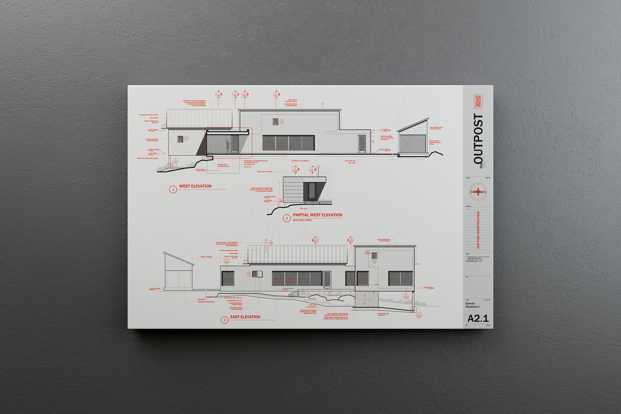
I use hatches to shade in the exterior walls – what architects call poche – in this drawing it’s an 80% screen on a solid hatch so color 208 on the hatch layer. I use hatches to indicate materials: like wood flooring, concrete block or tile patterns and I also use them for shade and shadow to call attention to something important in the drawing. On floor plans I use a variety of scales of dot pattern hatches on say descending stairs or as angled lines to show a partial height wall or cabinetry or a countertop surface. I also use solid screened hatches on all my glazed surfaces on exterior elevations, from between 40 and 60% screening. I use them in for the tree backgrounds too the ones you see here in the elevation drawings. I basically use them everywhere I can because they help call attention to things that are important and they add a softness to the drawing that I think looks I don’t know, painterly I guess.
Scale elements: By adding furniture, scale figures, cars, trees and other elements to indicate scale you’ll introduce a real sense that your architecture is meant to be inhabited. Doing this also ensures you’re accommodating the regular elements your end users will need to functionally use the architecture as well. Knowing your client wants to use an 8’ sofa will help you locate the floor outlets nearby and ensure it’s not obstructing a door swing.

When you’re drawing plans it’s good to begin thinking about materials and systems too. It’s okay if you’re missing this information early on and you’re working on conceptual plans, but I like to begin with at least some idea of how I’ll be constructing the building. For example, is it a masonry exterior? Is there a glass curtain wall? Concrete, wood framed walls, finishes, each of these materials has a thickness and when you start to turn corners and add jogs or if you begin intersecting different buildings or surfaces, knowing what those materials are becomes really important when you’re drawing.
Your final floor plan drawing can be as general or as detailed as you’d like, but the more detail you imbue your drawing with, the more useful a tool it will be later on when you’re drawing column details or figuring out how the glazed wall meets the concrete retaining wall. When I begin drawing a plan, I choose a wall thickness and some basic finishes as a starting point. So here I started by laying out the exterior face of the stud wall on the superfine layer. For our squid cove project we actually started with a double 2x4 stud wall on the exterior spaced apart to prevent thermal bridging. So I offset the outer perimeter by three and a half inches the width of a 2x4 wall, and then a quarter inch for the break, then another three and a half for the inner stud wall. Then I offset the interior finish thickness of ½” for the gypsum wallboard, then on the outside 1/2” for the exterior sheathing and another inch for the exterior shingled walls, Now, along the way, as the pricing came back for the double 2x4 wall system it was a lot more expensive than we anticipated so we had to change it back to 2x6 walls. Now, because windows take a long time to fabricate, this change actually happened after our windows had been ordered and so those openings were fixed on the plan, we had to use those openings. So, we were left with this detail at the interior corners to resolve. Knowing the actual systems and sizes of everything around them allowed us to design the trim around the windows that not only matched the detailing on the rest of the project but made it look like it was an intentional design decision. So when you can, show finishes. They also fill in this fine layer of linework that makes the contrast between thick and thin really pop.
Lastly, sort of the icing on the cake, we have the annotations. Annotations round out the information you’re conveying on the plan. They’re really important wayfinding tools for the contractor so they need be very clearly organized. I use red text to make it clear that the annotations are a part of another ordering system and also something they need to pay attention to. And, the ink is just pennies more to print them in color, honestly…I think it’s so worth it. You could make it blue or gray too, whatever you choose. I like the red because it’s easy to point to a note and say, it’s noted in red, hard to miss, right? This works in both directions by the way, so if it’s your mistake it’ll be pretty apparent! Annotations describe things you’re not able to draw, they reference other drawings and details, and should all be on the ‘text’ layer so you can turn them on and off as needed for presentation or while you’re making other changes to the plan. Annotations grow over time, they’ll be basic at first things like room labels and they’ll get progressively more numerous as you make design decisions. Now, I’m begging you please…please, please…don’t use those hand-lettered fonts…just uninstall those from your computer. I use Franklin Gothic for mine, but anything but the chiseled pseudo-hand lettering should be fine.
You’ll know you’ve done this all correctly when you squint your eyes and you can easily see what’s important. Do the walls stand out? Do the annotations fade. As you spend more time looking for information, more information should become apparent, almost like a pull focus or slow reveal. Light lines of the hatches should be the first to fade and last to come into focus.
So that’s it, I hope it was helpful!
If you want my template, there are two versions available:
AutoCAD template
Revit template
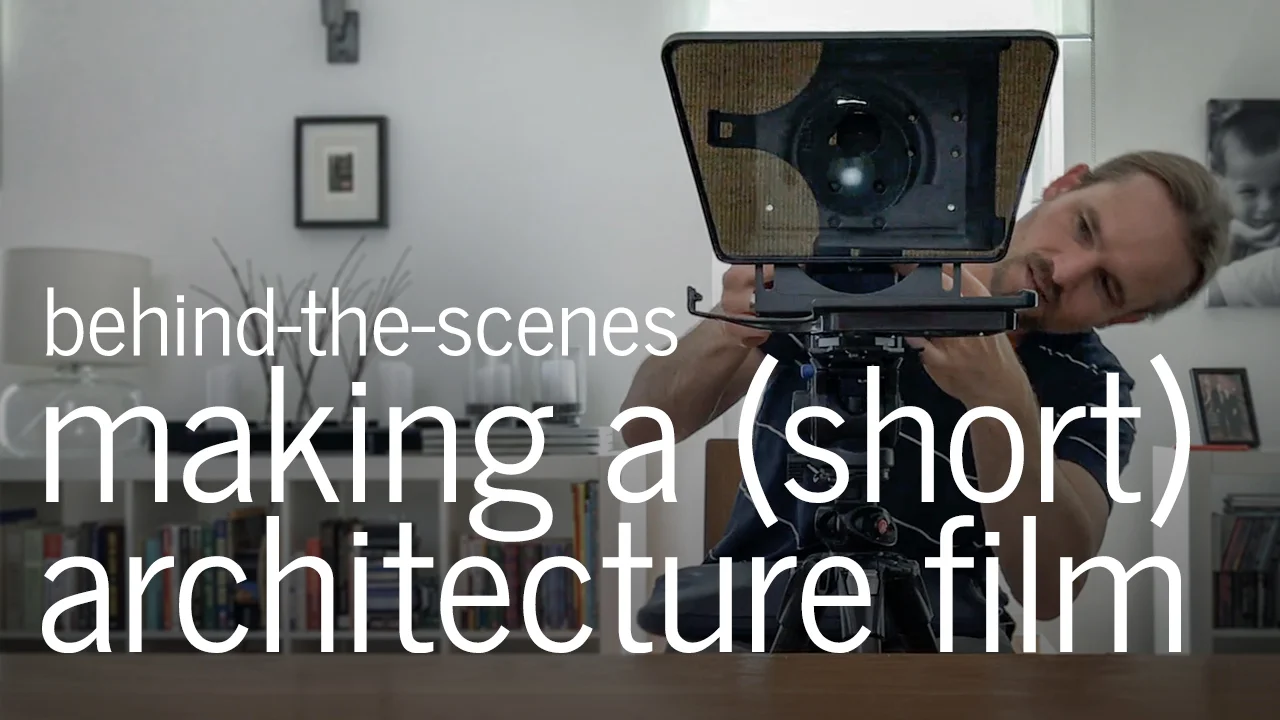
Making a Short Architecture Film | Behind-the-Scenes
A behind-the-scenes look at the making of a short architecture film. I commissioned this project - a collaboration with Trent Bell Photography - to introduce a little creative friction in my life and architecture practice. I've been thinking about making a documentary film for a long time and this was the year I decided it was time to stop talking about it and make it happen.
Along the way I learned the importance of story and script, how to craft an emotional narrative, how to collect and compose stunning visuals and I expect there's even more ahead as we edit and turn our ideas into reality.
This short vlog catalogues the two-day shoot.
The process indulged my curiosity about film-making and forced me to engage and learn from other professionals with far more experience than I in story-telling and film production.
This project was treated like everything in my architecture practice: as an experiment and it proved to be a wellspring of new ideas and approaches; exceeding my expectations.
Architecture takes a long time to make. In this way, the short film is a much more immediately gratifying creative outlet. I'd encourage all architects, students and fans of architecture to experiment with it in practice. If you ask similar things of your architecture that you do of a film you may find some surprising inspiration and outcomes.
My deepest thanks to Elise DeRosa for helping me find the story amongst a sea of ideas. To Corey for all his technical support, his keen eye for detail and for fearlessly facing the ravenous bugs here. And, special thanks to Trent for his expert vision and relentless drive to get things aesthetically perfect. I so enjoyed working with you.
I'm excited to share the finished product with all of you shortly. Stay tuned and thanks as always for sharing and supporting my work.
Developing the Concept: Architecture Short Course (part 2)
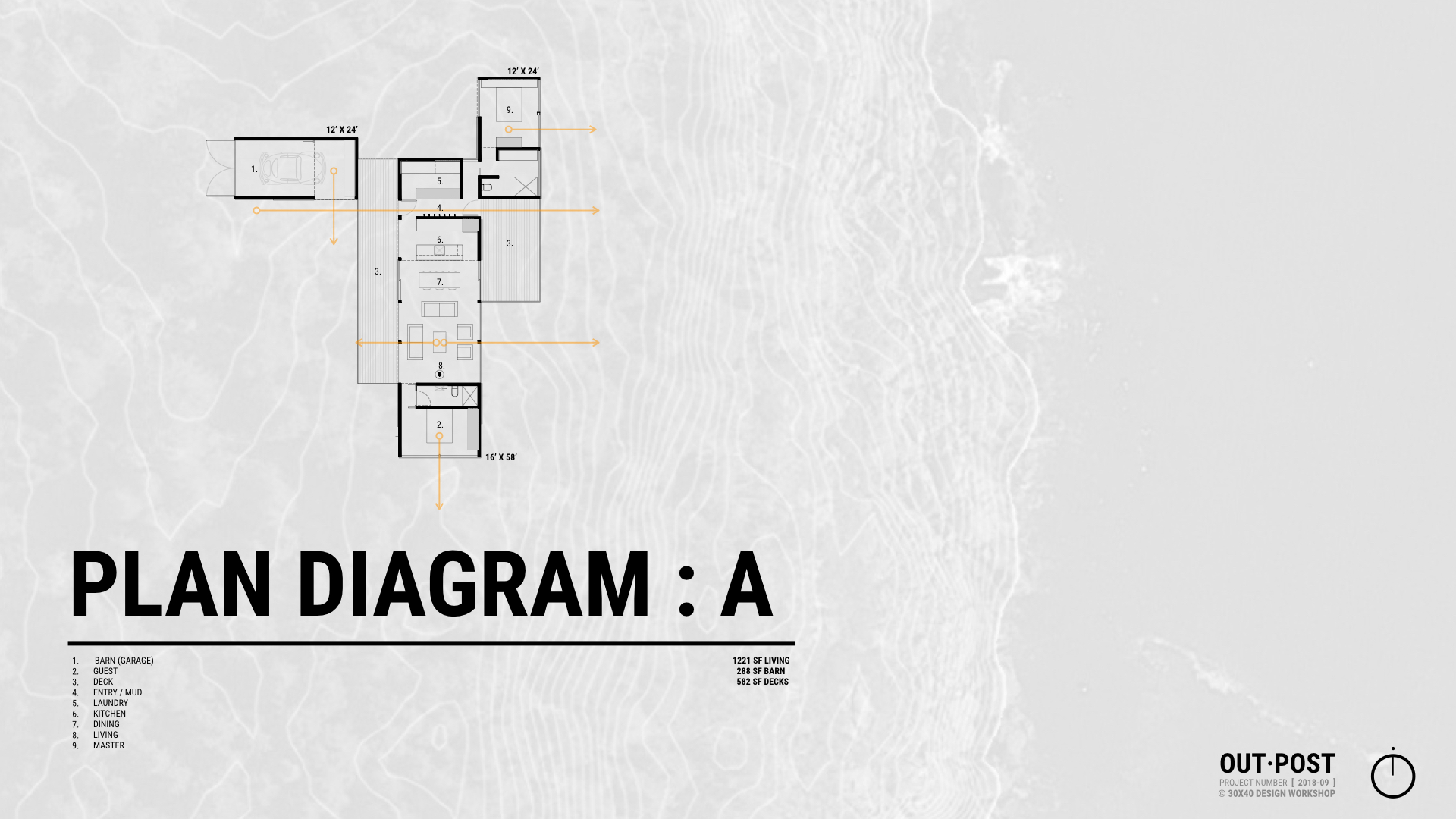
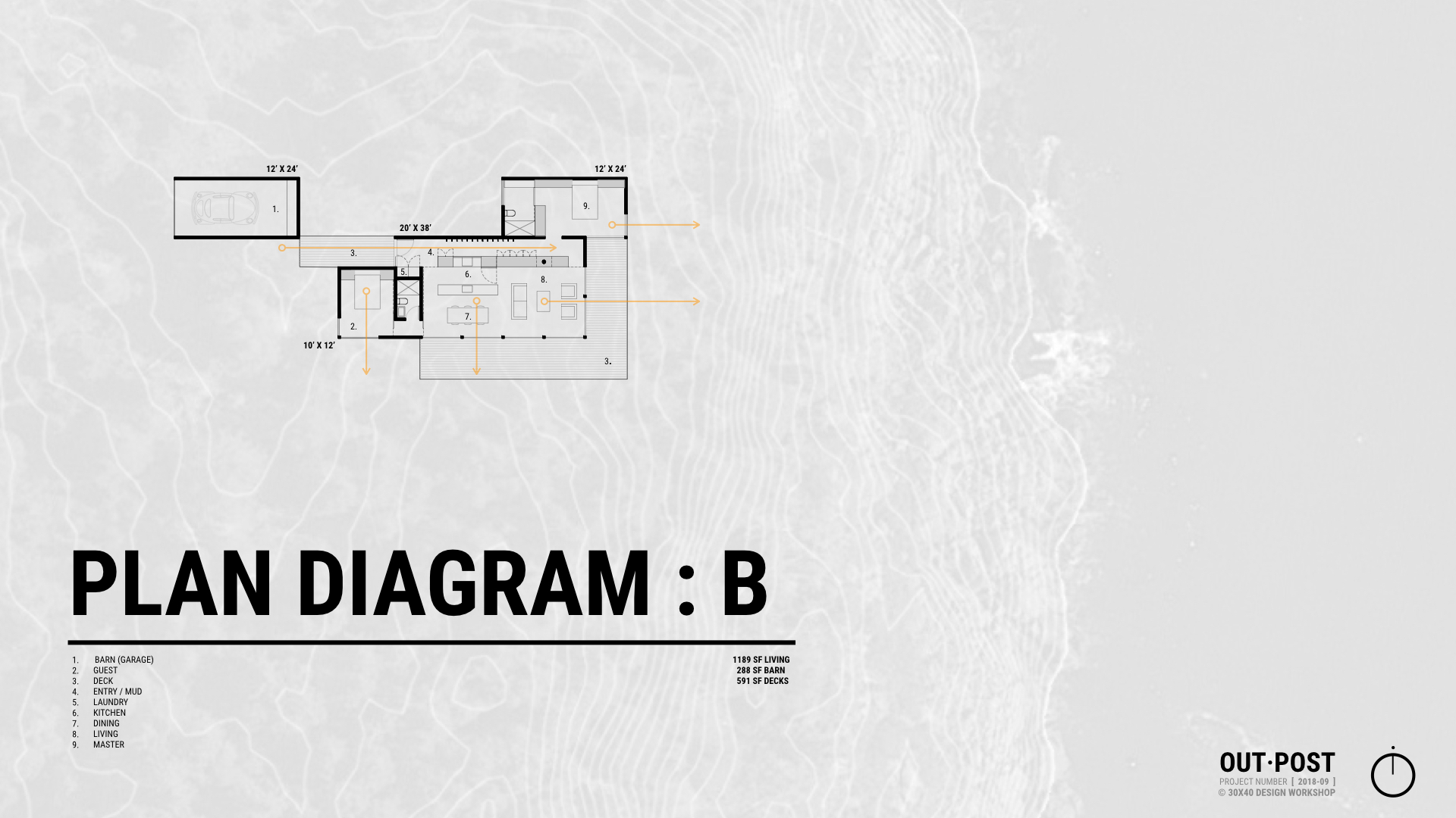
Developing the architectural concept into floor plans, designing the form, and refining the spatial ideas are all covered in part 2 of our architecture short course.
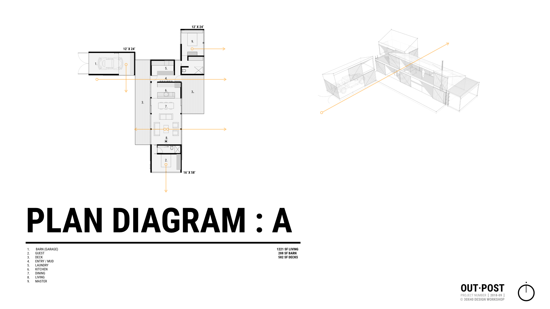
The first step in making the abstract concept real is to sketch a floor plan and then give that plan a three-dimensional form. A floor plan is a quick way of describing the hierarchy and relationship of spaces and it begins fixing their real physical dimensions and shapes. Throughout the design process architects must continually consider the design in both the plan, or overhead view, and the sectional, or volumetric view. The easiest way I’ve found to do this is to begin by sketching a plan and then construct a three-dimensional version of that plan either in model form or by sketching.
In order to get to three dimensions, we have to make some decisions about form, space, and order. When we speak about form we’re referring not only to a building’s shape but also to its size, scale, color, and texture…basically, all the visual properties of an object. Form has a direct relationship to space in that it influences both interior and exterior rooms. And lastly, order is how we choose to orient and relate the forms and spaces to each other. This directs the inhabitant’s experience of a place.
We'll review strategies for refining the floor plan, designing meaningful building forms, editing, and converting two-dimensional abstract concepts into three-dimensional buildings.